


|
|
|
|

Click on a robot above to view what it sees through it's camera
Robot Parts and Accessories
Accessories
(camera, gripper, speakers, microphone)
Sensors
(sonar, laser, tabletop)
System
(motor/wheels, onboard PC/software, wireless ethernet)
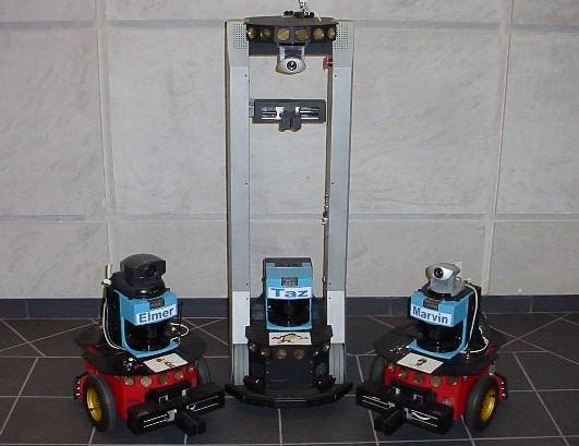
The robot being used for this project is the Performance PeopleBot, pictured above in the center, manufactured by ActivMedia Robotics. The robot is primarily a research tool for the Southern Illinois University Edwardsville (SIUE) School of Engineering. The robot was purchased during the Fall term of 2001 for approximately $40,000, including all of the additional options. The robot is an intelligent mobile robot that comes from the family of Pioneer robots. The robot runs on a client-server architecture and was first introduced to the public in the year 2000. The robot is approximately 124cm tall and weighs 21kg. To learn more about the accessories that came with our robot, read on or follow one of the links provided above.
Camera
 |
 |
|
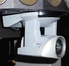
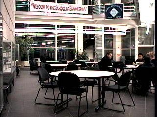
The camera used by our robot is a pan-tilt-zoom camera. The camera has the ability to move around and get a closer look at objects while the robot is moving. For our purposes, the camera will remain stationary facing in a forward direction. This will allow people to get a perspective of what it looks like from the view of the robot as it moves around the building. The camera is also capable of sending images back through a wireless network. According to ActivMedia, the camera is ideal as a surveillance system when used to remotely send images back to a computer. The photo in the upper left is a photo of the camera mounted on the robot, while the photo in the upper right is an actual photo taken by the robot. |
|
Gripper
 |
|
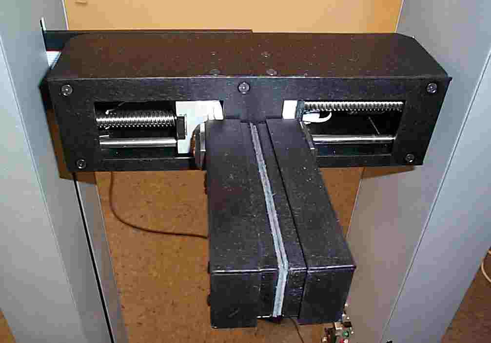
The gripper is exactly what the name implies. It is used to grasp objects from tables. The gripper can be used to move objects around a room or to simply hold onto an object indefinitely. The gripper has the ability to move up and down along the rails of the robot to accommodate differing heights of tables. A switch under the gripper paddles indicate that they've dropped to the table's surface. Horizontal break beams between the gripper's paddles indicate that an object is available to be picked up. Below is a list of technical data on the gripper. |
Speakers/Microphone
 |
 |
|
The sound system in the PeopleBot is fully integrated into the server software. The speakers can play sound files or synthesized speech input into the onboard PC. The microphones provide the ability to follow speech commands recognized with IBM's Via Voice speech recognition software. The robot comes with several audio demos for playback. Our team does not plan to utilize the sound system during this project but this is an interesting idea for future projects with this robot. |
|
Sonar
 |
 |
|
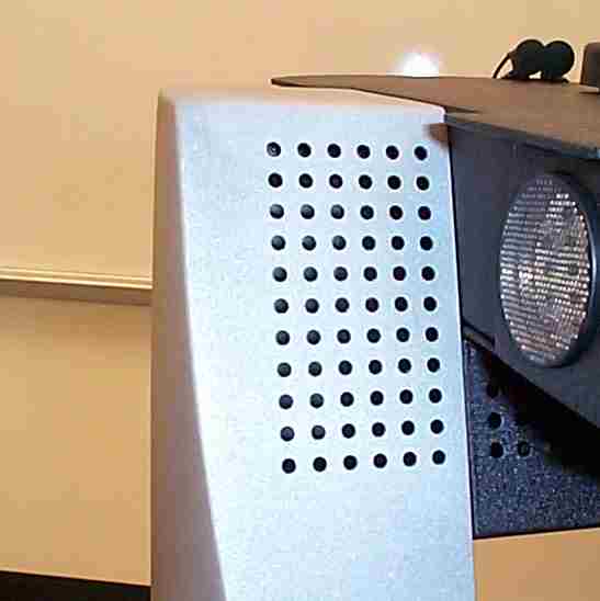
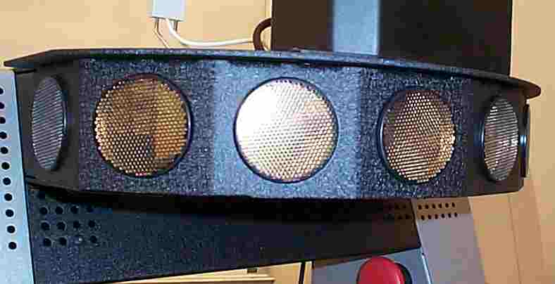
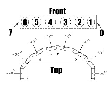
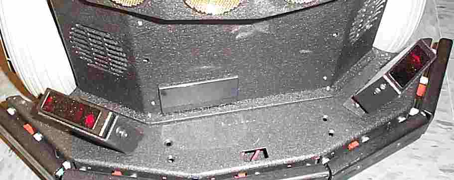
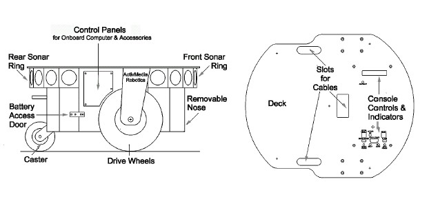
The sonar is the primary means of navigation for the robot. The sonar works in much the same way as bats. The sonar sends out a pulse that sounds like a click and then listens for a return signal. The speed that the signal returns determines the distance the robot is from an obstacle. During normal operations, the sonars fire in sequence from 0 to 7 along the array as shown in the diagram. The sequence can be changed if the programmer feels the need. The robot supports a full complement of 32 sonars in up to 4 arrays. As the photo shows, the sonars are arranged in arrays of 8. The sonar arrays are located at the top and bottom of the front and at the bottom of the back of the robot for nearly seamless 360 degree coverage. The position of each sonar is fixed in the array as shown in the diagram. Each sonar comes with its own electronics for independent operation. The sensitivity and range can be re-calibrated for different environments. The sensitivity may need to be adjusted lower if the robot is moving over uneven terrain such as a thick shag carpet. The robot may see the carpet as an obstacle if the sensitivity is set too low. Increasing the sensitivity on a smooth surface allows the robot to see objects at a greater distance. |
|
Laser Range Finder
 |
|
 |
|
|
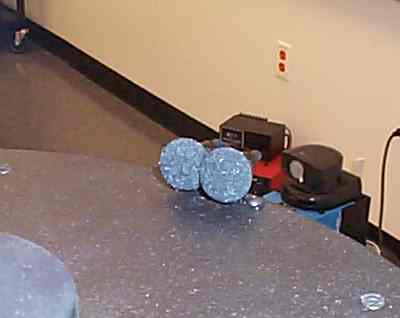
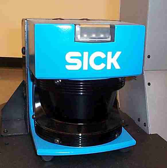
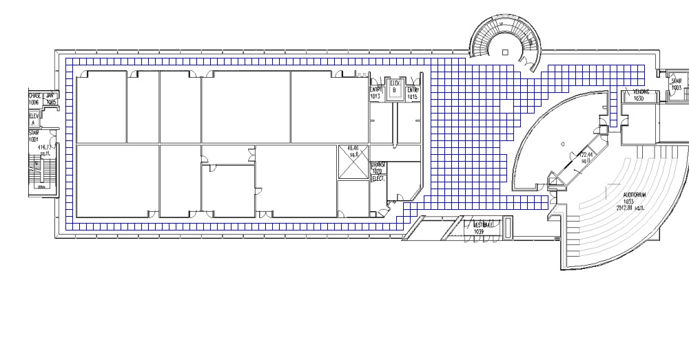
The laser range finder is an improvement upon the sonar array. The
laser shoots a beam and measures the distance to where the beam hits an
obstacle. The laser is significantly more precise than the sonar, but the range
is limited. Used in conjunction with the sonars, the robot can autonomously
navigate around obstacles. The photo that looks like a blue coffee pot is the
actual laser mounted on the robot. The diagram is the internal map that the
robot uses to determine where it is on a map. The grid points serve to show the
robot where it can and cannot go. This allows us to control the robot from
going to forbidden places, such as a stairwell and the elevators. |
|
Tabletop Sensor
 |
|
The tabletop sensor is used in conjunction with the gripper to determine the height of tables, barriers and other obstacles that otherwise aren't detectable by the other sensors. Very reliable diffuse infrared detectors are mounted to the front of the robot. The sensors are oriented up and slightly forward of the robot to detect objects that pass within approximately one foot of the robot. The sensor range is limited to improve accuracy. This means that the beam is too short to reach the ceiling. The sensors can respond to any surface, except glass or other mirrored surfaces, and can detect objects as thin as a human finger. The sensors utilize breakbeam technology, sensing when an object passes into the space of the robot. |
Motor/Wheels
 |
 |
|
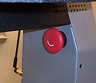
Wheels The robot has 2 pneumatic wheels 191mm in diameter and 1 caster, 75mm in diameter, used for balance. The differential drive platforms are highly holonomic and can rotate in place moving both wheels, or can swing around a stationery wheel in a circle of 32cm radius. The wheels can support up to a 13kg payload. The payload includes a full complement of batteries and all accessories. For effective operation, the payload must be properly balanced. The robot can also move at a maximum speed of .8 meters per second and traverse a maximum step of 1.5cm The wheels can cross a maximum gap of 5cm plus climb a maximum of a 5% grade. The robot can typically go anywhere that a wheelchair has access to. The wheels have 500-tick encoders to provide less than 1% dead reckoning error. Motor The drive system uses a high speed, high torque, reversible DC motor. The motor is equipped with a high resolution optical quadrature shaft encoder for precise position and speed sensing and advanced dead reckoning. The motor is powered by up to 3 hot-swappable 7 ampere hour 12 volt DC sealed lead/acid batteries for a total of 252 watt-hours. Charge life typically runs between 2-3 hours, however, without using the motors, the robot will survive for several days without recharging. Management of the motor is under software control. Normally, the motor is disabled when not connected to a client. You must press and release a button on the robot to activate the motors. If not connected to a client, the button merely serves to put the robot in a joydrive mode. Power can be cut instantly by a large red button, as shown in the photo, inside the body of the robot near the top. The button must be deactivated to restart the robot's. 2 motors. |
|
Onboard PC/Software
Onboard PC
In the client-server architecture, the onboard PC acts as the server for commands sent to the robot. The user must supply their own PC to run the client software. The client computer must be a 586-class computer or later with Microsoft Windows 9x/ME or RedHat Linux Operating System. Several clients can simultaneously connect to the server to control the robot. The onboard PC allows the robot to be an autonomous agent. It handles the low level details of robotics including maintaining speed and heading over rough terrain, acquiring sensor readings, and managing the accessories. The onboard PC uses a high performance 20MHz Siemens 88C166-based microcontroller with independent motor/power and sonar controller boards. The controller has 2 RS232-standard communication ports and an expansion bus to support the many accessories available as well as custom attachments. It also comes with a 32K flash-programmable read-only memory (FLASH-ROM) and an additional 32K of dynamic RAM.
Software
The operating system used by the onboard PC is the P2OS. P2OS, named for the Pioneer 2 series, is a robotics server software operating system. ActivMedia maintains a software support line available 24 hours a day and 7 days a week for technical support. The typical software that comes standard on the robot includes Navigator, Worldlink, Mapper, Simulator, ARIA and Saphira. Navigator is a sophisticated graphical user control program allowing you to access the many intelligent sensors. Worldlink is basically Navigator on the network. It lets you remotely connect to the robot and control the robot from anywhere in the world. Mapper provides the ability to construct a map of the world around you. Simulator is an application for testing your programming in an environment before installing on the robot. The Activmedia Robotics Interface for Applications, ARIA, is a C++ based open-source development tool for creating client-side interfaces to communicate with the onboard operating system and accessories. ARIA handles low level details of client server interactions. Saphira is a robot control environment founded on ARIA. Saphira is used extensively by the prepackaged software for robotics controls. Watchdog software is included to test for client communication. If the communication is cut for a set time, the robot is shut down automatically. Once communication is restored, the motors are automatically restored.
Wireless Ethernet Communications
 |
|
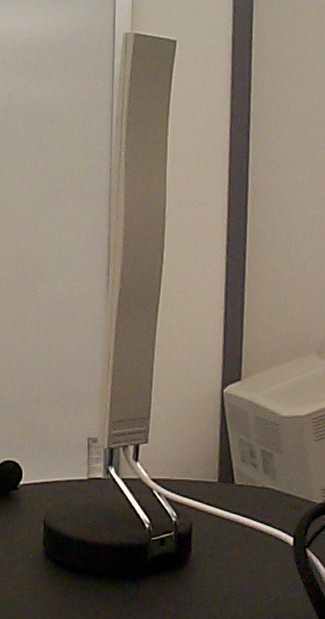
The wireless ethernet connection allows the robot to become truly autonomous. The robot is given the ability to receive commands and send information back through an antenna mounted on top of the robot. For the purposes of our project, the wireless ethernet will allow the team to provide access to the robot over the Internet. Users will be able to tell the robot which way to move and see live images without a cord dragging around behind the robot. This is critical for safety of the robot and people around it. If communication is lost, the robot will shut down in place and wait for communication to be restored. |
|
URL:http://www.roboti.cs.siue.edu/ourrobot.htm Published by: Network Operated Robotics Research Team Last update: 2/10/03 by Webmaster |
|

